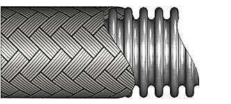
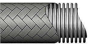
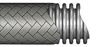
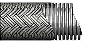
Corrugated
metal
hoses
come
in
many
configurations.
These
tools
can
help
ensure
you
select
the
right
corrugated
metal
hose
for
your
application.
There
are
many
components
in
a
metal
hose
assembly
and
care
should
be
taken
when
selecting
each
of
them.
Moreover,
the
components
have
their
own
unique
technical
limitations
so
it
is
important
to
make
sure
each
of
the
components
is
compatible
with
your
application.
In
much
the
same
way
as
a
“chain
is
as
strong
as
its
weakest
link”,
a
metal
hose
assembly
will
only
perform
to
the
limits
of
its
weakest
component.
Once
the
components
have
been
selected,
the
quality
and
skill
of
the
fabricator
assembling
the
components
becomes
important.
The
procedures
and
care
used
when
fabricating
assemblies
also
has
a
dramatic
effect
on
the
assembly’s
overall
performance.
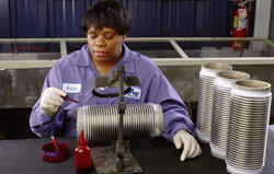
Hose
Master
has
invested
a
considerable
amount
of
resources
to
researching
metal
hose
fabrication
and
developing
a
state-of-the-art
fabricating
center.
In
addition,
we
share
the
welding
technology
we
have
developed
with
our
fabricating
distributors.
All
of
this
is
done
to
promote
quality
and
consistency
in
fabricating
metal
hose
assemblies.
In
this
section,
we
will
discuss
the
various
components
that
make
up
a
corrugated
metal
hose
assembly,
and
what
information
a
metal
hose
fabricator
will
need
in
order
to
make
an
assembly
for
your
application.
If
you
need
assistance
determining
the
information,
we
have
also
included
an
explanation
of
how
to
analyze
the
application
and
make
the
appropriate
selections.
Specifying
a
Corrugated
Metal
Hose
Assembly:
In
order
to
make
an
assembly,
the
fabricator
will
need
answers
to
the
following
five
questions.
For
more
information
about
any
of
these
questions,
or
for
a
list
of
available
options,
click
the
topic
heading
for
a
more
detailed
explanation.
-
Hose (type,
alloy,
and
size)
-
End
Fittings (type,
alloy,
and
size
for
each
end)
-
Length
of
the
assembly (either
overall
length
or
live
length)
-
Fabrication
options
-
Accessories
If
you
have
the
answers
to
these
questions,
a
metal
hose
fabricator
will
be
able
to
make
the
assembly.
If
you
do
not
know
the
answers
to
all
five
questions,
you
will
need
to
obtain
them.
The
next
section
is
designed
to
help
you
determine
the
answers.
Analyzing
an
Application:
To
properly
design
a
metal
hose
assembly
for
a
particular
application,
the
following
design
parameters
must
be
determined.
To
help
remember
them,
they
have
been
arranged
to
form
the
acronym
“S.T.A.M.P.E.D.”
-
Size –
The
diameter
of
the
connections
in
which
the
assembly
will
be
installed
is
needed
to
provide
a
proper
fit.
This
information
is
required.
-
Temperature –
As
the
temperature
to
which
the
assembly
is
exposed
(internally
and
externally)
increases,
the
strength
of
the
assembly’s
components
decreases.
Also,
the
coldest
temperature
to
which
the
hose
will
be
exposed
can
affect
the
assembly
procedure
and/or
fitting
materials.
If
you
do
not
provide
this
information
it
will
be
assumed
that
the
temperatures
are
70°
F.
-
Application –
This
refers
to
the
configuration
in
which
the
assembly
is
installed.
This
includes
both
the
dimensions
of
the
assembly
as
well
as
the
details
of
any
movement
that
the
assembly
will
experience.
This
information
is
necessary
to
calculate
assembly
length
and
required
flexibility.
-
Media –
Identify
all
chemicals
to
which
the
assembly
will
be
exposed,
both
internally
and
externally.
This
is
important
since
you
must
be
sure
that
the
assembly’s
components
are
chemically
compatible
with
the
media
going
through
the
hose
as
well
as
the
environment
in
which
the
hose
is
installed.
If
no
media
are
given,
it
will
be
assumed
that
both
the
media
and
the
external
environment
are
compatible
with
all
of
the
available
materials
for
each
component.
-
Pressure –
Identify
the
internal
pressure
to
which
the
assembly
will
be
exposed.
Also,
determine
if
the
pressure
is
constant
or
if
there
are
cycles
or
spikes.
This
information
is
important
to
determine
if
the
assembly
is
strong
enough
for
the
application.
If
no
pressure
is
given
it
will
be
assumed
that
the
pressure
is
low
and
there
are
no
pressure
surges
or
spikes.
-
End
Fittings –
Identify
the
necessary
end
fittings.
This
is
required
since
fittings
for
the
assembly
must
be
chosen
to
properly
fit
the
mating
connections.
-
Dynamics
–
Identify
the
velocity
at
which
the
media
will
flow
through
the
assembly.
Since
corrugated
metal
hose
does
not
have
a
smooth
interior,
rapid
media
flow
can
set
up
a
resonant
frequency
that
will
cause
the
hose
to
vibrate
and
prematurely
fail.
If
no
velocity
is
given,
it
will
be
assumed
that
the
velocity
is
not
fast
enough
to
affect
the
assembly’s
performance.
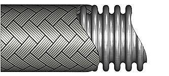
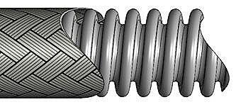
Stress-Lite CorrugaTed Metal Hose
Discover the Power of Stress-Lite™
When it comes to manufacturing corrugated metal hose, minimizing residual stress during the formation of corrugations is crucial. Hose Master has revolutionized this process with its Stress-Lite™ technology, featuring Hydroforming and Crimpforming methods.
Why Choose Stress-Lite™?
Unlike other methods that induce excessive residual stress and potentially shorten the product's lifespan, Stress-Lite™ employs proprietary gentle forming technologies. These processes eliminate the twisting of the tube that often leads to harmful torsional stress, fatigue, and premature failure.
The Innovation Behind Stress-Lite™
Stress-Lite™ annular hose processes synchronize non-torsional radial forming with simultaneous bi-directional axial tube feed. This advanced technique results in hoses with:
- Minimal Work Hardening
- Uniform Wall Thickness
- No Residual Torsional Stress (RTS)
Experience Exceptional Performance
With Stress-Lite™, you benefit from:
- Greater Flexibility
- Higher Cycle Life
Choose Stress-Lite™ for superior performance and reliability in your metal hose applications.
Processes of Manufacturing:
Crimpforming vs Hydroforming
-
Crimpforming Process
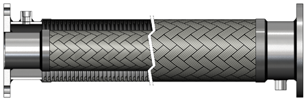
Crimpforming method grabs a section of tube, compresses it without torsion using a “shutter-crimp”, while simultaneously feeding the tube in axially from both directions.
-
Hydroforming Process
Hydroforming method grabs a section of tube, expands it without torsion using high pressure water, while simultaneously feeding the tube in axially from both directions.
-
Crimpforming Process
Crimpforming compresses the tube from the outside, and is used on more ridged tube having a larger t/d (tube thickness to diameter) ratio.
-
Hydroforming Process
Hydroforming expands the tube from the inside.
Our engineers at Hose Master have developed Stress-Lite™ processes which represent the state-of-the-art technology in hose manufacturing. This, in conjunction with an optimized hose profile, yields the best corrugated metal hose in the industry.
Stress-Lite™ Products
-
Is the standard of Hose Master’s extensive line of high performance Stress-Lite™ annular corrugated stainless steel hose. Proprietary technology ensures the excellent cycle life of the hose, with minimum effort to flex or bend the hose.
-
Hose Master’s close pitch metal hose. It is manufactured using the same high quality process used to make Annuflex hose, but the number of corrugations per foot is increased to allow for greater flexibility.
-
Hose Master’s high-pressure, annular corrugated metal hose. Pressureflex HP® is made from heavy-wall stainless steel, and offers flexibility and dependability when higher pressures are a factor.
-
Hose Master’s annular, heavy-wall corrugated metal hose, designed for ULTRA high-pressure applications. PressureMax HP® offers superior flexibility and is made from heavy wall T321 or T316L stainless steel.
-
Hose Master’s chemical transfer hose. Chemking™ offers excellent corrosion resistance to many of the most severe applications found in chemical processing.
-
Hose Master’s 276 alloy, corrugated chlorine-transfer assembly, designed to meet the demands of this application. With considerations made for both wet and dry chlorine, these assemblies are the safest available.
-
Has the “stay-put” characteristics required for stress-free connections between piping systems and rotary joints or other similar static applications.
-
Heavy-duty corrugated hose designed for use in applications that require a bronze hose.
-
Hose Master’s T321 spirally-welded, helical corrugated hose specifically designed to achieve extreme flexibility while maintaining good pressure ratings. The helical design facilitates draining and reduces in-line turbulence.
-
Hose Master’s T316 double-walled, spirally-welded corrugated metal hose. Specially designed to maintain extreme pressure and flexibility, Hydraflex™ is self-draining and generates minimal in-line turbulence.
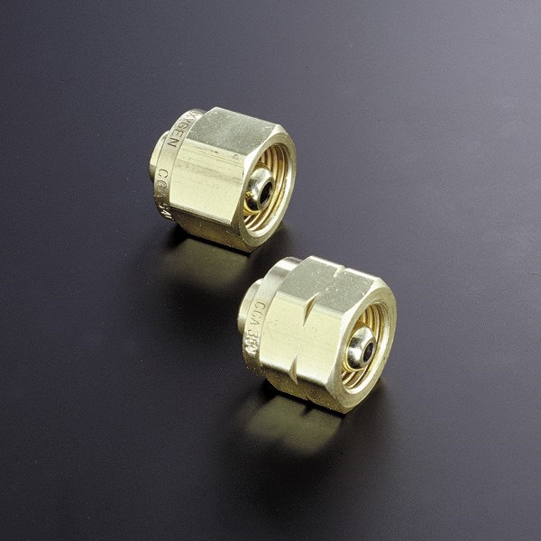
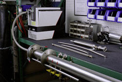
Fittings
Metal
hose
is
more
versatile
than
other
hose
in
that
virtually
any
fitting
can
be
attached
to
metal
hose.
Other
types
of
hose
require
special
shanks
and
collars
in
order
to
attach
fittings.
For
metal
hose,
any
fitting
made
from
a
weldable
material
can
be
attached
without
the
need
for
special
features.
This
versatility
also
means
that
multiple
fittings
can
be
welded
together
to
make
custom
solutions
for
difficult
applications.
Selecting
the
proper
fittings
for
an
application
is
largely
determined
by
the
mating
fittings
to
which
the
hose
assembly
will
be
attached.
Once
the
mating
fittings
have
been
identified,
the
hose
fittings
should
complement
the
mating
fittings
in
type,
size,
and
alloy.
Even
though
the
selection
of
hose
fittings
is
determined
by
the
mating
fittings,
it
is
a
good
idea
to
confirm
that
the
fittings
used
in
the
application
are
appropriate
for
the
application
and
any
necessary
changes
made.
Ensure
that
the
fittings
are
chemically
compatible
with
and
are
able
to
withstand
the
pressure
and
temperatures
of
both
the
media
and
the
surrounding
environment.
The
following
show
commonly
used
fittings
for
corrugated
metal
hose
assemblies.
Please contact Hose
Master’s
Customer
Service
Department
for
end
connections
that
are
not
listed.
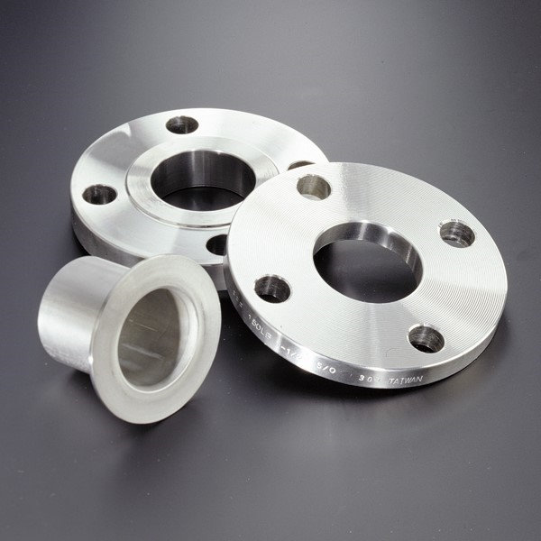
-
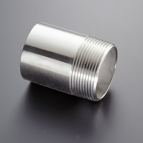
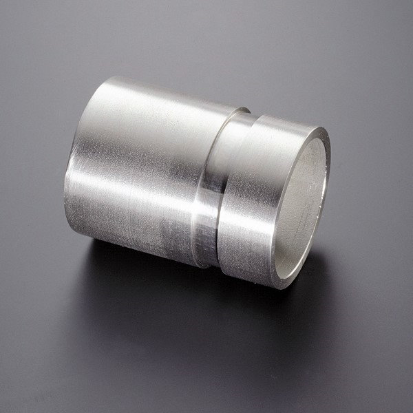
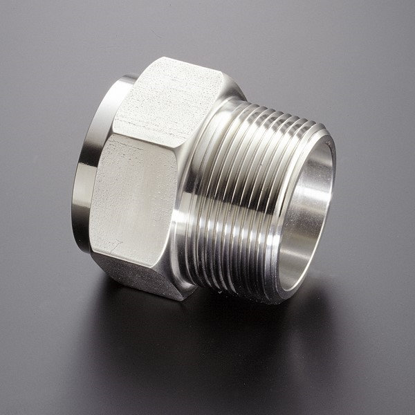
Male Pipe Nipple
- Alloys – T304 and T316 Stainless Steel, Carbon Steel, 276
- Sizes – 1/8″ thru 8″
- Schedules – 40 and 80
-
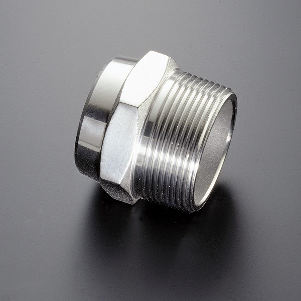
Hex Male
- Alloys – T304 and T316 Stainless Steel, Carbon Steel, Brass
- Sizes – 1/4″ thru 4″
-
Grooved-End Fitting
- Alloys – T304 and T316 Stainless Steel, Carbon Steel
- Sizes – 1″ thru 8″
- Schedule – 40
-
LiveLink® Swivel Fitting
- Alloys – T304 Stainless Steel
- Sizes – 1/4″ thru 2″
-
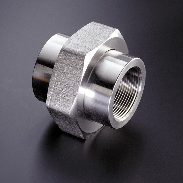
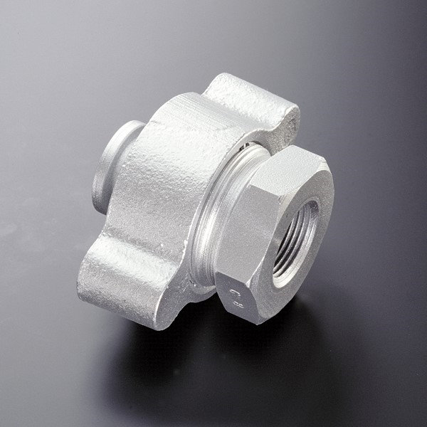
Female Union (Threaded/Socket Weld)
- Alloys – T304 & T316 Stainless Steel, Carbon Steel, Malleable Iron, Brass
- Sizes – 1/4″ thru 4″
- Class – 125#, 150# (3000# Carbon Steel Only)
-
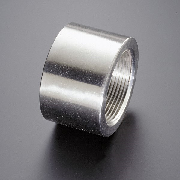
Female Half Coupling (Threaded/Socket Weld)
- Alloys – T304 and T316 Stainless Steel, Carbon Steel
- Sizes – 1/4″ thru 4″
- Class – 150# (3000#)
-
1, 2, or 3 Piece SAE (JIC)
- Alloys – T316 Stainless Steel, Carbon Steel, Brass (nut only)
- Sizes – 1/4″ thru 2″
-
45° and 90° SAE (JIC)
- Alloys – Stainless Steel, Carbon Steel
- Sizes – 1/2″ thru 2″
-
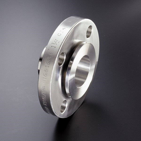
Sanitary Flange
- Alloys – T304 and T316 Stainless Steel
- Sizes – 1″ thru 3″
-
Slip-on Flange
- Alloys – T304 and T316 Stainless Steel, Carbon Steel
- Sizes – 1/2″ thru 12″
- Class – 150#, 300#
-
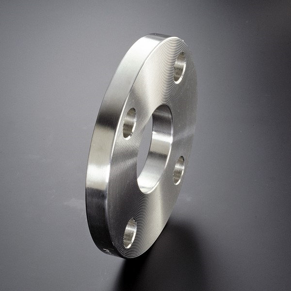
Plate Flange
- Alloys – T304 and T316 Stainless Steel, Carbon Steel
- Sizes – 1/2″ thru 12″
- Class – 150#
-
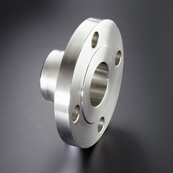
Weld Neck Flange
- Alloys – T304 and T316 Stainless Steel, Carbon Steel
- Sizes – 1/2″ thru 6″
- Class – 150#, 300#
-
TTMA Flange
- Alloys – T316 Stainless Steel, Carbon Steel
- Sizes – 2″ thru 6″
-
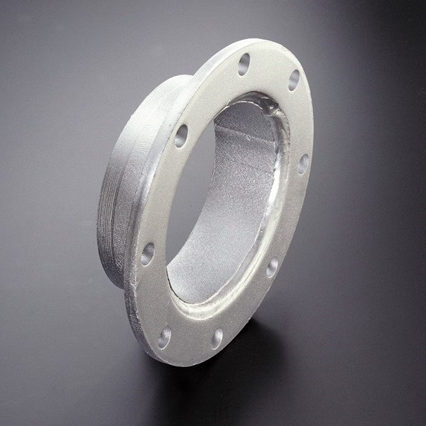
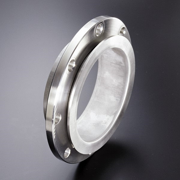
C Stub with Floating Flange
- Alloys – T304 and T316 Stainless Steel
- Sizes – 1/2″ thru 10″
- Schedule – 10
-
A Stub with Lap Joint Flange
- Alloys – T304 and T316 Stainless Steel, Carbon Steel, 276
- Sizes – 1/2″ thru 8″
- Schedules – 10, 40
-
TTMC C Stub Swivel
- Alloys – T304 and T316 Stainless Steel
- Sizes – 4″ thru 6″
- Schedule – 10
-
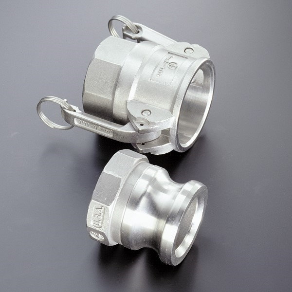
Part A and Part D (Cam-Lock)
- Alloys – T316 Stainless Steel, Brass, Aluminum
- Sizes – 1/2″ thru 8″
-
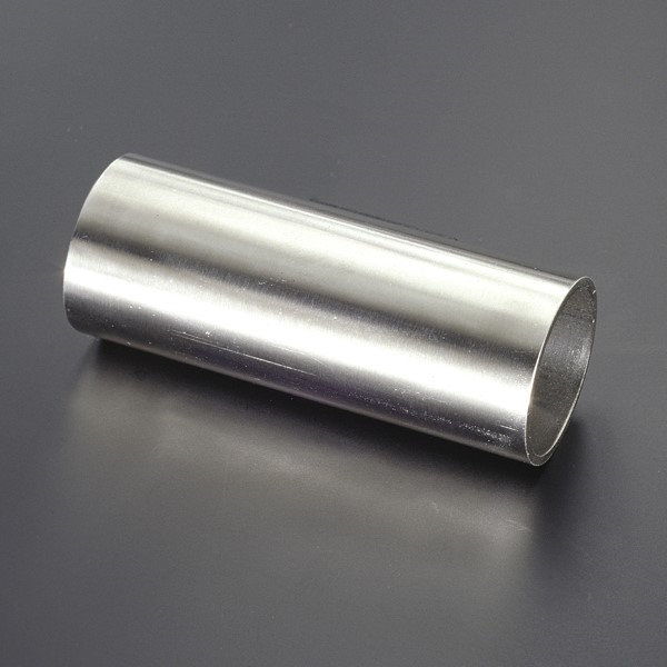
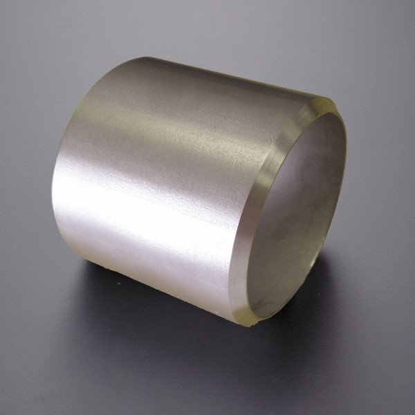
Tube End
- Alloys – T304, T316, and T321 Stainless Steel, Carbon Steel
- Sizes – 1/8″ thru 8″ (seamless and welded)
- Wall Thickness – various
-
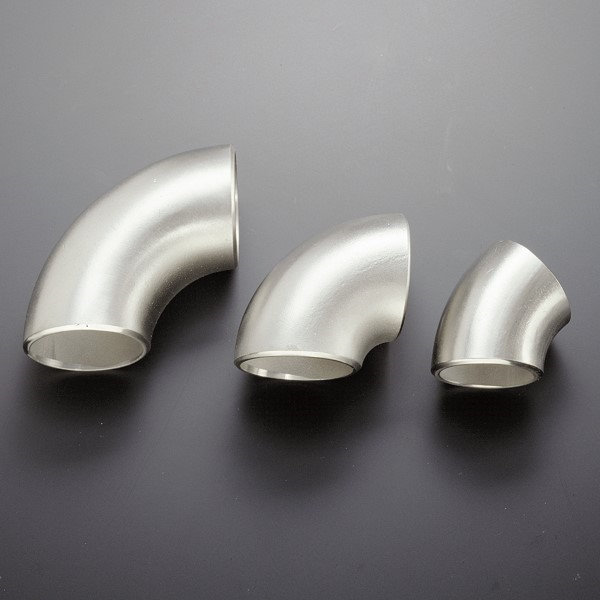
Short and Long Radius Elbows (45° and 90°)
- Alloys – T304 and T316 Stainless Steel, Carbon Steel, 276
- Sizes – 1/4″ thru 6″
-
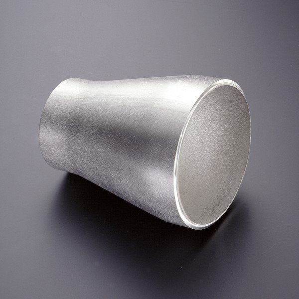
Reducer
- Alloys – T304 and T316 Stainless Steel, Carbon Steel
- Sizes – 3/4″ thru 6″
- Schedule – 10 (40 Carbon Steel)
-
Beveled Pipe End
- Alloys – T304 and T316 Stainless Steel, Carbon Steel, 276
- Sizes – 1/8″ thru 8″
- Schedules – Various
-
Ground Joint Female
- Alloys – Carbon Steel
- Sizes – 1/2″ thru 4″
-
Specialty Gas Nuts
- Alloys – Brass
- Sizes – A, B, C, D
- Thread Type – SAE and BSP
Hose Master places emphasis on continual improvements within our manufacturing processes, product offering and services. Hose Master reserves the right to make changes without further notice to any products contained herein.
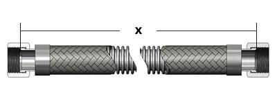
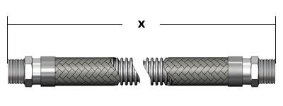
To
calculate
the
proper
length
of
a
hose
assembly:
-
Verify
that
the
installation
is
properly
designed
You
can
see
our illustration of
the
right
and
wrong
ways
to
install
a
hose
assembly.
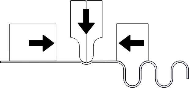
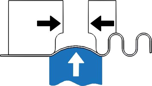
Basically,
there
are
three
considerations:
-
Do
not
torque
the
hose.
-
Do
not
overbend
the
hose.
-
Do
not
compress
the
hose.
-
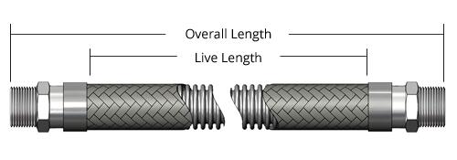
Calculate
the
live
length
of
the
assembly
The
live
length
of
the
assembly
is
the
amount
of
active
(flexible)
hose
in
an
assembly;
that
is,
the
hose
between
the
braid
collars.
See
the Length
Calculation chart
for
more
information.
-
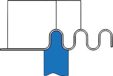
Calculate
the
overall
length
of
an
assembly
Overall
length
is
equal
to
the
live
length
plus
the
lengths
of
the
braid
collars
and
fittings.
When
adding
fitting
lengths
be
aware
that
the
points
from
which
measurements
should
be
taken
vary
for
different
fitting
types.
When
calculating
overall
length
for
assemblies
with
threaded
fittings,
remember
to
account
for
the
length
of
thread
that
is
lost
by
threading
into
the
mating
connection.
See
the Thread
Allowance chart
for
more
information.
-
JIC/SAE
type
fittings
are
measured
from
the
seat
of
the
fitting.
-
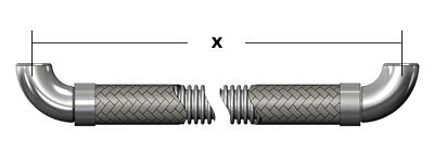
Elbows
and
other
fittings
with
a
radius
are
measured
from
the
centerline
of
the
fitting.
-
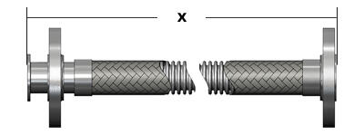
Flanges
are
measured
from
the
flange
face
or
from
the
face
of
the
stub
end
if
one
is
used.
-
Threaded
fittings
are
measured
to
the
end
of
the
fitting.
Hose
Master
places
emphasis
on
continual
improvements
within
our
manufacturing
processes,
product
offering
and
services.
Hose
Master
reserves
the
right
to
make
changes
without
further
notice
to
any
products
contained
herein.
Fabrication
Options
Corrugated
metal
hose
is
used
in
a
very
broad
spectrum
of
applications.
Just
as
the
hose,
fittings,
and
other
assembly
parts
must
be
tailored
to
suit
the
demands
of
the
service,
so
must
the
methods
of
joining
these
components.
While
standard
production
joining
methods
work
very
well
for
the
majority
of
service
demands,
the
following
extremes
may
dictate
special
joining
or
fabrication
techniques:
-
Pressures
-
Temperatures
-
Corrosion
-
Other
conditions
Hose
Master
has
developed
specialized
welding,
brazing,
joining,
and
fabrication
procedures
to
assure
the
integrity
and
serviceability
of
metal
hose
assemblies
in
even
the
most
extreme
applications.
The
fabrication
options
to
be
considered
are:
-
Specialized
attachment
techniques
-
Testing
options
-
Additional
cleaning
requirements
-
Packaging
In
each
of
the
following
sections,
the
standard
method
and
available
options
are
explained.
Select
the
options
best
suited
for
your
application.
Specialized Attachment Techniques
Industry Standard
This method will be used unless another method is specified
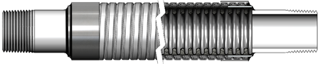
Standard fabrication of an assembly generally consists of:
- Cutting the hose and braid through a hose corrugation valley.
- Installation of a braid collar over each end of the hose.
- Trimming of any excess braid.
- “Cap” welding the hose, braid, and braid collar together.
- Cleaning the cap weld surface.
- Placement and alignment of a fitting on the cap weld.
- “Attachment” welding the fitting to the cap weld.
- Silver brazing is also available. Consult factory.
Half-Corrugation
Standard fabrication sometimes leaves a portion of the cut corrugation, or corrugation “lip”, just under the base of the fitting. In specialized applications this residual lip may not be desirable. To prevent any exposed corrugation edges from causing damage, the hose can be specially prepared for welding by cutting the corrugation on the crest, rather than in the valley, thereby removing the lip.
Smooth Transition Weld
For applications in which corrosion is a concern, all crevices and fissures must be minimized. Specialized hose and fitting preparation, in conjunction with proprietary welding techniques, is available to provide a full penetration hose-to-fitting weld that is smooth and crevice free.
Braid-Over Construction
Assemblies operating at the upper limits of their rated working pressure or in severe service may benefit from a braid-over construction. The fitting is first welded to the unbraided hose. Then a special metal reinforcing ring is installed over the fitting and next to the weld. Finally the braid is drawn over the end of the hose and the ring, and welded to the side of the fitting. This technique reduces the amount of heat introduced into the braid wires, nearly eliminates the heat effected zones of the cap and attachment welds, and maximizes the wire strength. Braid-over construction may also be used for specific high cycle applications.
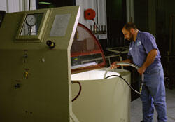
Testing Options
Note: Always test an assembly with a medium that has a smaller molecular or atomic size than the service required.
Standard Leak Testing
Every corrugated hose assembly is leak tested prior to shipment. Standard testing consists of pressurizing the assembly with air and then submerging the entire assembly under water. This method is reliable and sufficient for the majority of applications.
Hydrostatic Testing
While the standard test is designed to detect leaks, hydrostatic testing is designed to test the assembly’s strength. Testing of an assembly to its full permissible test pressure can be economically and accurately accomplished by filling the assembly with liquid while concurrently evacuating all air. The assembly is then hydrostatically pressurized using high pressure pumps. The test pressure is maintained for a predetermined period of time.
High Pressure Gas
Testing with air under water, at pressures of up to 2500 psi, is available for specialized applications. For a more sensitive test, the use of gases such as nitrogen or helium can be requested.
Dye Penetrant
Dye penetrant testing is available for both leak and for weld bead inspection, in accordance with Hose Master procedures or to customer specified standards.
Helium Mass Spectrometer
This is the most sensitive leak detection method generally available. The standard test method is to attach the assembly to a mass spectrometer and generate a very high vacuum in the assembly. The exterior of the assembly is then flooded with helium. The relatively tiny helium atoms penetrate even very small openings and are drawn into the mass spectrometer where they are detected and the leak size quantified. Helium Mass Spectrometer testing can be modified to satisfy customer or regulatory agency requirements.
Additional Cleaning Requirements
The hydroforming method of corrugated hose manufacturing inherently yields a very clean product. However, specialized cleaning for specific applications is available upon request. Contact Hose Master’s Customer Service Department for details.
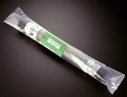
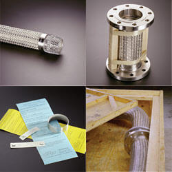
Packaging
All assemblies are shipped with protectors over sealing surfaces such as threads and flange faces. Spacer bars are installed on all shorter double-flanged assemblies to prevent compression of the assembly during shipping and handling. Special packaging is available to suit customer requirements, including crating, plastic bagging, labeling, and custom fitting protectors.
Hose Master places emphasis on continual improvements within our manufacturing processes, product offering and services. Hose Master reserves the right to make changes without further notice to any products contained herein.
Accessories
Metal
hose
assemblies
often
require
special
accessories
or
components
in
order
to
provide
long
service
life
in
severe
applications
or
make
the
assemblies
easier
to
use.
There
are
many
accessories
that
may
be
specified
including:
-
Guard,
made
from
metal
and
other
materials,
can
be
provided
to
protect
an
assembly
from
overbending,
abrasion,
impact,
and
thermal
damage.
-
Jacket
and
tracer
hoses
are
incorporated
into
corrugated
hose
assemblies
in
order
to
keep
certain
media
at
elevated
or
reduced
temperatures
so
that
it
can
be
easily
conveyed.
-
A
sacrificial
bronze
braid
can
be
inserted
between
the
hose
and
the
stainless
steel
braid
to
improve
cycle
life.
One
or
several
accessories
can
be
easily
combined
with
an
assembly
to
more
efficiently
transport
media,
protect
the
assembly,
or
both.
The
following
pages
list
some
common
accessories
along
with
a
brief
explanation
of
the
benefits
each
accessory
offers.
This
is
not
an
exhaustive
list
of
all
possible
accessories.
Please
contact
Hose
Master’s Customer
Service
Department with
your
specific
requirements.
Spring Guard
When there is potential for damaging an assembly in service, a guard can be easily installed during fabrication. This type of guard consists of a metal spring that is attached behind the fitting. The style of guard can be tailored to meet the application and the type of hose.
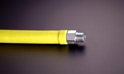
Protective Cover
If the potential for impact or high temperature damage is not severe, or if the additional weight and bulk of a full metal guard is unacceptable, rubber or plastic scuff guards can be installed to protect the corrugated hose and braid.
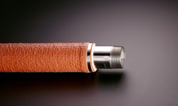
Insulating Jackets
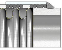
If the corrugated hose is to convey hot media, and there is a potential for skin contact, an insulated, protective jacket is available. The jacket consists of a tubular banded fiberglass insulation, covered and impregnated with silicone rubber. The jacket is installed over the corrugated hose and metal banded in place. The jacket can also be used to insulate the corrugated assembly and either prevent ambient heat from being conveyed to the media or to reduce heat loss.
Tagging
A variety of tags and identifications can be affixed to assemblies. These include cardboard, plastic, and metal tags. Serial numbers, application information, assembly performance capabilities, and other customer specific information can be provided either on tags or permanently engraved onto one or both braid collars.
Certifications
Standard written certifications for materials or inspections can be supplied for corrugated hose or assemblies. Certifications of conformance to specific customer requirements such as military certifications are also available.
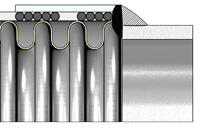
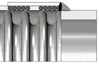
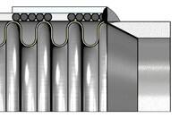
Liners
An interlocked hose or liner is often installed inside a corrugated hose assembly. The liner commonly serves two additional purposes, while still maintaining the full working pressure of the corrugated hose. The first is to protect the hose corrugations from excessive media velocities. Media speeds can induce resonant vibrations in the corrugations causing rapid fatigue and subsequent fracturing of the hose wall. The liner provides a relatively smooth surface for the media and, by avoiding the media impacting on the corrugation valleys, reduces the chances of harmonic resonance. The second purpose for a liner is for abrasion resistance. Even slightly abrasive media flowing at medium to high speeds can cause premature wear of the corrugated hose interior surfaces. The liner provides a smooth flow path as well as a relatively thick layer of abrasion resistant metal between the media and the corrugated hose. The liner will also help reduce pressure loss due to friction between the media and corrugated hose. Proper fit between the hoses is essential for good performance. Because Hose Master makes both the corrugated hose and liners, perfect fit is assured. See the Velocity in Metal Hose chart for more information.
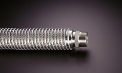
Armor Guard / Bend Restricter
Applications in which the corrugated hose is subject to external abrasion, molten material splash, or impact damage may require a protective armor or guard along all or a portion of its length. A guard is typically made from interlocked or squarelocked metal hose and is welded to the assembly. Note that the bend restricter has a bend diameter equal to or greater than the corrugated hose it is protecting.
Jacketed Assemblies
A jacketed assembly consists of a “hose within a hose.” An inner or primary media conveying hose is enclosed or jacketed by a larger diameter hose. The hoses are joined at each end by specially designed fittings so that there is no media pathway between the two hoses. Jacketed assemblies are often specified when the primary media must be kept at either an elevated or cryogenic temperature. Steam is often circulated through the jacket hose to keep a viscous material in the inner hose hot and easily conveyed. A vacuum can also be pulled on the jacket hose to insulate cryogenic liquids being conveyed in the inner hose.
Tracers
Traced assemblies are similar in concept to jacketed assemblies in that there is an inner, smaller diameter hose encased by a single larger diameter hose. Where jacketed assemblies surround the media with heat or cold, traced assemblies have the media surround the hose containing the heating or cooling element. The tracer, or inner hose, may also be installed in a long “U” shaped loop within the outer hose, with the steam inlet and outlet at the same end of the assembly.
Hose Master places emphasis on continual improvements within our manufacturing processes, product offering and services. Hose Master reserves the right to make changes without further notice to any products contained herein.