Corrugated Metal Hose Products
Stress-Lite CorrugaTed Metal Hose
Discover the Power of Stress-Lite™
When it comes to manufacturing corrugated metal hose, minimizing residual stress during the formation of corrugations is crucial. Hose Master has revolutionized this process with its Stress-Lite™ technology, featuring Hydroforming and Crimpforming methods.
Why Choose Stress-Lite™?
Unlike other methods that induce excessive residual stress and potentially shorten the product's lifespan, Stress-Lite™ employs proprietary gentle forming technologies. These processes eliminate the twisting of the tube that often leads to harmful torsional stress, fatigue, and premature failure.
The Innovation Behind Stress-Lite™
Stress-Lite™ annular hose processes synchronize non-torsional radial forming with simultaneous bi-directional axial tube feed. This advanced technique results in hoses with:
- Minimal Work Hardening
- Uniform Wall Thickness
- No Residual Torsional Stress (RTS)
Experience Exceptional Performance
With Stress-Lite™, you benefit from:
- Greater Flexibility
- Higher Cycle Life
Choose Stress-Lite™ for superior performance and reliability in your metal hose applications.
Processes of Manufacturing:
Crimpforming vs Hydroforming
-
Crimpforming Process
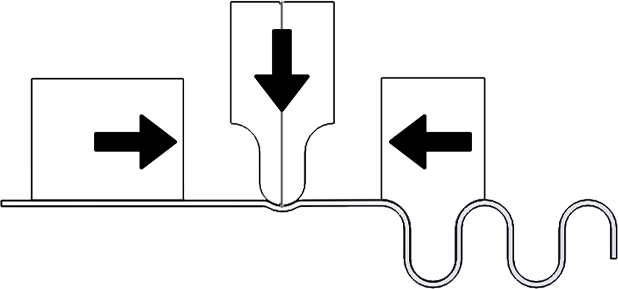
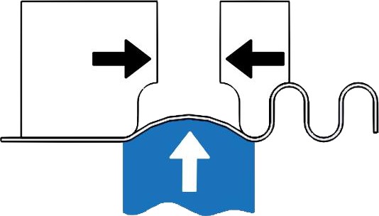
Crimpforming method grabs a section of tube, compresses it without torsion using a “shutter-crimp”, while simultaneously feeding the tube in axially from both directions.
-
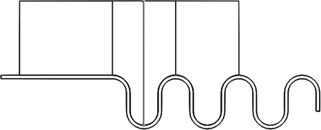
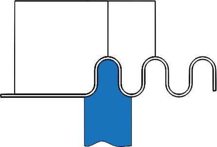
Hydroforming Process
Hydroforming method grabs a section of tube, expands it without torsion using high pressure water, while simultaneously feeding the tube in axially from both directions.
-
Crimpforming Process
Crimpforming compresses the tube from the outside, and is used on more ridged tube having a larger t/d (tube thickness to diameter) ratio.
-
Hydroforming Process
Hydroforming expands the tube from the inside.
Our engineers at Hose Master have developed Stress-Lite™ processes which represent the state-of-the-art technology in hose manufacturing. This, in conjunction with an optimized hose profile, yields the best corrugated metal hose in the industry.
Stress-Lite™ Products
-

Annuflex™
Is the standard of Hose Master’s extensive line of high performance Stress-Lite™ annular corrugated stainless steel hose. Proprietary technology ensures the excellent cycle life of the hose, with minimum effort to flex or bend the hose.
-

Masterflex
Hose Master’s close pitch metal hose. It is manufactured using the same high quality process used to make Annuflex hose, but the number of corrugations per foot is increased to allow for greater flexibility.
-

PressureFlex HP®
Hose Master’s high-pressure, annular corrugated metal hose. Pressureflex HP® is made from heavy-wall stainless steel, and offers flexibility and dependability when higher pressures are a factor.
-

PressureMax HP®
Hose Master’s annular, heavy-wall corrugated metal hose, designed for ULTRA high-pressure applications. PressureMax HP® offers superior flexibility and is made from heavy wall T321 or T316L stainless steel.
-

ChemKing®
Hose Master’s chemical transfer hose. Chemking™ offers excellent corrosion resistance to many of the most severe applications found in chemical processing.
-

ChlorSafe™
Hose Master’s 276 alloy, corrugated chlorine-transfer assembly, designed to meet the demands of this application. With considerations made for both wet and dry chlorine, these assemblies are the safest available.
-

Formaflex™
Has the “stay-put” characteristics required for stress-free connections between piping systems and rotary joints or other similar static applications.
-

Bronzeflex™
Heavy-duty corrugated hose designed for use in applications that require a bronze hose.
-

Extraflex™
Hose Master’s T321 spirally-welded, helical corrugated hose specifically designed to achieve extreme flexibility while maintaining good pressure ratings. The helical design facilitates draining and reduces in-line turbulence.
-

Hydraflex™
Hose Master’s T316 double-walled, spirally-welded corrugated metal hose. Specially designed to maintain extreme pressure and flexibility, Hydraflex™ is self-draining and generates minimal in-line turbulence.
-
When to Use Flexible Metal Products
-
Select the Right Hose for Your Application
-
Select the Right Corrugated Metal Hose
-
Select the Right Stripwound Metal Hose